

Directional control valves in hydraulics – areas of application and designs
Directional control valves are used in all hydraulic applications, both stationary and mobile. Hydraulic directional control valves are components that control the flow of a pressurized fluid in terms of start, stop, quantity and direction. They make piping connections by opening, closing, or changing one or more flow paths.
Hydraulic valves
in directional valve design are a standard component and part of almost all hydraulic systems. A movable actuator is brought into certain positions (switching positions) by actuating elements directly or indirectly via a pilot stage, thus establishing a corresponding line connection.
To meet the different requirements and operating conditions, directional control valves are offered in different switching variants. In doing so, a variety of line connections are achieved through different piston shapes without having to modify the housing. The requirements for different volume flows are met by selecting different nominal valve sizes.
Directional valves are used in all areas of hydraulics, both stationary and mobile.
Switching positions and connections
Hydraulic directional control valves have a variety of connections and switching positions that require a unique designation. Each switch position is represented by a square; arrows and dashes inside the square indicate the connection between the terminals. Depending on the number of different switch positions, a symbol consists of several squares. The simplest form of directional control valve has two ports and two switching positions. The effect of the different switching positions is illustrated by the displacement of the switching positions relative to the fixed line connections. The designation of the ports of a directional control valve P, T, A, B and L is made on the square which is in the rest or home position.
Structure of a directional control valve symbol

The name of the directional control valve is preceded by the number of controlled ports and switching positions, e.g. directional control valve with 3 controlled ports and 2 switching positions: 3/2 – directional control valve (hydraulic).
Hydraulic directional spool valves
The most commonly used type of directional control valve is the hydraulic directional spool valve.
In the case of valves with a longitudinal spool design, a piston is located in the housing in which annular grooves are screwed in. The longitudinal movement of the piston causes the annular grooves present in the housing to be connected or disconnected. This directs the flow of the liquid.

In spool valves, sealing occurs along a gap between the moving spool and the body. The degree of tightness depends on the gap size, the viscosity of the medium and, in particular, the pressure head. At high pressures (up to 350 bar), leakage losses occur in an order of magnitude that must be taken into account when determining the efficiency of the system
4/3-way valve hydraulics (spool valve) – explanation of operation

The above figure shows the operation of a 4/3-way gate valve. When the piston has been switched to the right (Fig. a), the flow is opened from P to A and from B to T. If the valve spool was actuated to the left (figure c), port P is connected to B and A to T. In this example, the switching of the piston to its end positions is realized hydraulically, i.e. the corresponding piston sides are pressurized with control oil. The center position of the piston is achieved by the spring centering. In the zero position, all connections are shut off from each other (Fig. b). The above 4/3-way hydraulic valve therefore has 4 controlled ports (A, B, P and T) and 3 switching positions (left, center, right).
Types of directional control valve actuation
In the case of directly controlled directional spool valves, the spool is controlled directly by solenoids, pneumatic/hydraulic cylinders or by a mechanical device.
Directly controlled directional control valves are usually designed in hydraulics only up to nominal size 10 (CETOP 5). The maximum flow rate is approx. 120 l/min. The background to this is the static and dynamic forces that occur at the directional spool valve as a result of pressure and flow.
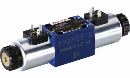
Electromagnetic actuation
The electromagnetic type of actuation is the most common. One must still distinguish between DC and AC solenoids in solenoid actuation. The linear solenoids are used in the following basic designs:
- In air switching solenoid (dry solenoid)
- DC solenoids switching in oil (“wet” solenoid, with the solenoid armature running in oil).
- AC solenoid switching in air
- AC solenoid switching in oil
The DC solenoid has the advantage that it does not burn out in the event of mechanical jamming and has a long service life. In contrast, the AC solenoid enables a short switching time.
In directional spool valves, solenoids switching in oil are predominantly used today.
3-chamber and 5-chamber directional control valves
Directional spool valve according to the 3-chamber principle
In a directional spool valve according to the 3-chamber principle, only the ring channels P, A and B are sealed by the spool. The springs rest on the solenoid housing and center the piston in the zero position.

Directional control valve hydraulics according to the 5-chamber principle
In this type of valve, the T-channel is formed as a chamber by webs in the body on both sides, as are P, A and B. The two end spaces are connected via a hole. By installing a nozzle or an adjustable throttle in this connecting bore, the switching time can be influenced according to the nozzle diameter or the throttle position.
Mechanical, manual operation
Especially in mobile hydraulics, the hand lever is the most common operating element. Actuation is usually against a return spring (compression spring) for 2 switching positions. This holds the valve in the zero position as long as no actuating force is acting. If the valve has 3 switching positions, the center position (zero position) is usually held by the spring centering. The other two switching positions are reached by the actuating force. Hand lever valves are also available with detents in various switching positions.

Here, a valve piston is actuated by means of a hand lever. Here, the valve piston is connected to the actuating mechanism and follows its movement. There are compression springs in the valve which are responsible for the return of the piston. This means that after the actuating force has ceased (e.g. by releasing the hand lever), the valve piston is pushed back to its initial position.
In the valve version with detent, the switching position is fixed by the detent, the possibility of resetting the piston by the centering springs is omitted. Once a detented position has been reached, it can only be changed again by means of actuation.
Hydraulic or pneumatic actuation
With hydraulic actuation, the hydraulic control pressure acts directly on the valve spool via a piston.
In pneumatic actuation, the air pressure acts on an appropriately sealed piston. Normal pressure or low pressure of logic elements with single or multi-stage amplification can be used.
Pilot operated directional spool valves (indirect actuation)
Indirectly operated directional control valves are used to control larger volume flows. The reason for this is the high actuating forces required to move the spool.
Pilot operated hydraulic directional control valves consist of two elements, the hydraulically operated directional control valve and a small directly operated directional control valve. This is normally directly electrically operated. The small solenoid valve serves as a pilot valve and has the task of selectively directing pressurized fluid to one of the two piston sides of the hydraulically actuated directional control valve.

Thus, when the pilot valve is switched, the control signal is hydraulically amplified and the main control spool is displaced. In the spring-centered version, the main spool is held in the center position by the springs. In the initial position, the two spring chambers are connected to the tank without pressure. This is done by the pilot valve. This is supplied with sterile oil via the control line. It can be fed internally (tapped at pressure port “P”) or externally (via port “X”).
When the solenoid of pilot valve b is energized, the pilot piston is pushed to the right and the pilot oil acts on the right face of the main spool. This is now moved to the left against the spring force and releases the flow from P to A and from B to T.
When the solenoid of the pilot valve is de-energized, the pilot spool returns to the center position and the spring chamber is relieved. The spring can now push the piston of the main valve to the right until it rests against the spring plate of the spring. The control oil displaced from the spring chamber during the switching process flows off into channel Y via the pilot valve. The switching operation when the solenoid a is actuated runs analogously.
A minimum control pressure (approx. 4 bar) is required for switching. It can therefore only be controlled with the intrinsic medium if the minimum pressure is always present at P. Another variant for pilot operated directional spool valves is the version with pressure centering.
Directional valves hydraulics – switching overlap
The switching overlap provides information about the processes during the switching operation of the valve. A distinction is made between positive and negative switching overlap.

With positive switching overlap (circuit diagram 1/2), all connection channels are briefly shut off from each other during the switching process. When switching over, there are therefore brief pressure peaks, since the pump flow must be discharged via the pressure relief valve. Pressure peaks can be relieved with the help of hydraulic accumulators. The advantage of the positive switching overlap is that a load under load cannot drop when switching over.
With negative switching overlap (circuit diagram 0/2), all connection channels are briefly connected to each other during the switching process, the pressure “collapses”. This prevents pressure peaks, but a consumer under load may drop when switching.
Flow characteristics
The indication of the flow rate for a directional control valve hydraulics is only meaningful if it is related to the pressure difference. The pressure difference Δp is the difference between valve inlet pressure and valve outlet pressure and thus a measure of the internal resistance of the directional control valve. This is mainly caused by flow losses in the valve.

The pressure difference cannot be calculated exactly in practice, therefore the valve manufacturers determine the values empirically for the individual valve sizes (see example). The results are presented in the form of Δp-Q curves. Each connection of the individual switching positions is displayed (e.g. P-A, P-T,…).
Performance limits
When operating hydraulic directional control valves in the limit range, i.e. at maximum pressure and maximum volume flow, corresponding disturbance forces act on the valve spool depending on the circuit diagram. In the worst case, these can exceed the available actuating forces of solenoids and return springs. In these cases, application limits must be defined. These are also displayed graphically:

If a hydraulic directional control valve with too high a pressure and flow rate is selected, the valve spool may stop when the capacity limit is exceeded, even if a switching command has been given. The magnet then no longer manages to move the slider.