

What is the function of a hydraulic valve?
Hydraulic valves are an important part of hydraulic systems and control or regulate the flow of hydraulic fluid (usually oil). Hydraulic valves control e.g. start, stop and direction as well as pressure or flow of the pressure medium delivered by a hydraulic pump. Valves are important components in hydraulic systems and help to ensure that they operate precisely and reliably.
How does a hydraulic valve work?
The operation of a valve depends on the design. Basically, hydraulic valves are divided into so-called spool valves and poppet valves.
Gate valves usually have a control piston as a control element. This is moved within the housing bore. Depending on the position of the piston (spool) in the body bore, it either blocks or opens the connection between the channels in the valve body. The spool is guided in the housing with little clearance. The resulting liquid film between the components reduces friction. Spool valves are used, for example, with directional control valves.
Compared to spool valves, poppet valves have Seat valves as a control element a ball, a cone or a plate. The control element locks or closes the valve cover by being pressed onto the valve seat by a spring. The channel is opened against the spring force, usually by the hydraulic medium. Compared to gate valves, poppet valves are characterized by high tightness. Seat valves are therefore preferably used where hydraulic circuits have to be shut off without leakage. Examples of shut-off valves are, for example, pressure relief or check valves.
What are the types of hydraulic valves?
Hydraulic systems place high demands on hydraulic valves. Therefore, valves are required in a wide variety of installation methods. Basically, the construction types can be distinguished by the following installation methods:
- Panel-mounting valves (e.g. CETOP3)
- Valves for line installation
- Screw-in valves (also called cartridge valves) for block installation
- Intermediate plate valves
- Valves in disc design (also referred to as sandwich design)
- Monobloc valves
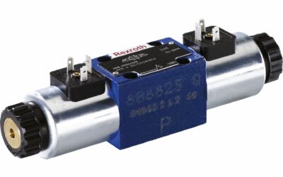
Hydraulic valves for the plate assembly
Valves of this type can be screwed onto a sub-base (valve base plate) or manifold plate as individual valves. They can also be used as the top component of an elevator linkage (e.g. for hydraulic power packs). Plate-mounting valves are usually so-called CETOP Valves. These have standardized connection holes and a standardized plate structure, which enables extremely space-saving installation. The standardized connection dimensions for the individual CETOP valve sizes can be found in ISO 4401.

Valves for in-line installation (pipeline valves)
Inline valves are installed directly in the hydraulic line and serve as intermediate elements. Hydraulic valves of this type are provided with threaded connections. Screw-in fittings are used for connection to hydraulic pipes or hose lines.

Screw-in valves (cartridge valves) for block installation
Screw-in valves are mounted directly in the screw-in bore of a control block or housing. The screw-in bore (many block manufacturers also refer to this as cavity) contains the central mounting thread and the holes for the hydraulic connections. It also provides appropriate sealing surfaces, depending on the valve design.

Intermediate plate valves
For sandwich plate valves, both the top and bottom surfaces form the mating surfaces. Both the connection and mounting holes are routed through the valves. For this reason, several valves can be built. Intermediate plate valves are usually used for vertical stacking.

Hydraulic valves in sandwich or disc design
With this design of hydraulic valves, individual functions can be flexibly combined with each other. Each “slice” contains the corresponding functionality required for the various control circuits. The individual valve discs are mounted or braced with the aid of tie rods.

Monobloc valves
In this design, the functions of several control circuits are contained in one housing. The advantage over sandwich valves is the smaller number of sealing surfaces. In addition, there are no restrictions due to tie rod forces. As a rule, the production of monoblock valves only makes sense for larger quantities. However, there are many standard designs that are also available in small quantities.

What is the symbol of the hydraulic valve?
The circuit symbols for hydraulic components are standardized in DIN ISO 1219:2012. Some examples of hydraulic valves can be found in the table:
Hydraulic valves contributions

Directional valve hydraulics
Directional control valves in hydraulics - areas of application and designsDirectional control valves are used in all hydraulic applications, both stationary and mobile. Hydraulic directional control valves are components that control the flow of a pressurized fluid...
Direct operated directional control valves in comparison
Hydraulic valves in comparisonThere are many manufacturers and distributors of direct acting hydraulic directional control valves. We have made the effort and compared the valves of some manufacturers on the basis of the data sheets. We have chosen a valve type that...

Lowering brake valves hydraulics
What is the function of a lowering brake valve in hydraulics? Overcenter valves (also known as counterbalance valves) are basically pilot-operated check valves with corresponding throttling and damping devices. These hydraulic valves regulate the lowering speed...